


This is a complete step-by-step guide on how to build a computer.
NOTE:The following images are used as an example & guide only. It may not represent the exact look of your part.
PREPARING
- only unbox things as they are needed. This will avoid mixing screws and parts.
- the only tools you'll need is a phillips screwdriver, a bowl and a pair of scissors. Use the bowl to store any screws or small pieces that you remove. An anti-static strap would be practical but you can always touch something metallic before any contact with your components to discharge any static electricity you could have.
- be very careful NOT do drop any metal parts, including screws inside the computer case, in or around the motherboard as it could short it and kill it.
- this step-by-step instruction list might seem long but most steps are easy and quick, so don't be scared!
1 - Case
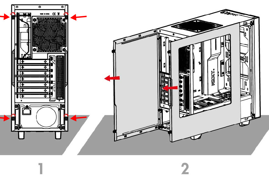


DO NOT INSTALL the motherboard yet: this illustration is only there to show you where the standoff could be installed.


2 - Power Supply
2-1 - Find out where the power supply mounting location is and install it there with the fan facing either outside if there is a vent or inside otherwise. It's usually in the bottom rear part of the case, but sometimes it can be in the top rear part. (don't add the screws yet)

2-3 - Add the 4 screws to secure it from the back of the case.
2-4 - If your case has some back-of-the-motherboard cable management space, use it to route all of the power supply cables. There should be grommets / holes around the motherboard to allow for that. That way, you can directly route under the motherboard SATA power cables from the power supply to the hard drives / SSD or disk drives.

2-5 - Some cases also have RGB lights or LED that you need to connect to the power supply. Look around the case, and especially under the other side panel of the case. If you find a molex or SATA power connector that is coming from the case and isn't connected, do so now.
2-6 - For now, we're done. You will connect the power cables in future steps.
3 - Motherboard
3-1 - Before you install the motherboard in the case, please make sure there aren't any loose metal parts or screws that fell in the case and could short the motherboard
3-2 - Remove the motherboard from its box and anti-static plastic bag and place it on the top of the closed box.
3-3 - By holding the motherboard firmly by the edges or the CPU heatsink, slowly and carefully place it inside the case, aligning the I/O toward the back of the case & aligning the screw holes with those in the case.
Do NOT slide the back of the motherboard as it could get scratched and damaged by the standoffs or other metal parts.


Do NOT over-screw: once you feel tension, add 1/4 turn and it should be enough.
Do not put too much pressure on the screwdriver as you could slip and damage the motherboard.


The headers should have wording like 'PW' or 'Power' for 'power', 'RS' or 'RES' or 'Reset' for 'reset', 'SP' or 'SPKR' or 'SPEAK' for 'speaker', 'HD' or 'HDD' for 'hard disk light' and so on. The abbreviations or naming could slightly different but it should be easy to find.
If you can't find any headers with those abbreviations, you'll need to refer to your motherboard's manual.


NOTE: make sure you look at the connectors to identify which side had no pin so you can align it properly with the motherboard header.


3-15 - Finally, if you case comes with an integrated audio out (headphone jack) and microphone jack then you'll need to connect another header that looks like the USB 2 one, but called 'HD AUDIO' or 'AC 97'.
Take note of the missing pin that you need to align when inserting the connector into the header.

4 - RAM / Memory
4-1 - Remove the RAM memory sticks from its box.
4-2 - Locate the RAM slots on the motherboard. There is only one place where the RAM sticks can go, so you can't go wrong.


4-4 - Using your two thumbs open the tabs of the RAM slots that you'll use.
4-5 - Looking at the stick of RAM, you'll see it has a NOTCH between the connectors. This is important.

4-6 - Please MAKE SURE that you line up the NOTCH of the RAM connector with those of the slot.

Warning: Do NOT FORCE the RAM. If it doesn't seem to go in easily, stop and check that everything is aligned and the notches match. Also, it's important to insert the RAM stick horizontally. DO NOT insert it at an angle (ex: one side first).

Warning: Do NOT FORCE the RAM. If it doesn't seem to go in easily, stop and check that everything is aligned and the notches match. Also, it's important to insert the RAM stick horizontally. DO NOT insert it at an angle (ex: one side first).
4-7 - If done properly, the tab(s) will pop in and secure the RAM automatically
5 - CPU

Warning: DO NOT TOUCH the CPU CONTACTS


5-5 - CAREFULLY place the CPU on the socket, aligning the TRIANGLE. DO NOT PRESS. DO NOT USE FORCE. It should just lay on top if aligned correctly. Give it a LIGHT wiggle to make sure you have a good fit.
5-6 - Close the retention arm & secure under the notch. The plastic cover should pop out by itself. Keep the plastic socket cover, you might need it if you sell your motherboard later
6 - Fans (CPU & Case)

6-2 - If your fan has a power wire wrapped around it, unwrap it now.

DON'T spread it, DON'T put more as it can affect negatively the cooling performance. Avoid touching thermal paste with hands as it could be toxic.
IMPORTANT: Avoid going too close to the sides as it could overflow and short the CPU (after the fan is added).

6-4 - Remove the protective sticker, if any, on the heatsink BASE. This would lead to trouble if left on.
Do NOT touch the heatsink base with your fingers.
Do NOT touch the heatsink base with your fingers.


6-6 - Secure the heatsink properly without over-thightning.
6-7 - Finish by connecting the fan power cable to the motherboard header. It should be located near to the CPU socket and named 'CPU FAN' (or similar). This is important as the connector could fit in many headers on your motherboard.

Warning: Do NOT connect it to the other headers (ex: SYS FAN, PUMP, RGB FAN) as it could cause the motherboard to think that it doesn't have a CPU fan and stop at boot.

7 - Hard Drive

7-2 - If the case has mounting brackets or adapters for the SSD / HDD:
7-3 - Remove the mounting brackets or adapters from the case drive bays
7-4 - Mount the SSD / HDD to the bracket using included screws.

7-5 - Install the SSD / HDD in the case drive bays.
7-6 - Connect one SATA data cable to the mobo SATA header & route it to the SSD / HDD. Please refer to your manual to find out which sata port to use for optimum speed. You should always start with "SATA_1", then 2, etc.


7-8 - Connect the other end to the SSD / HDD SATA port
7-9 - Now connect the SATA POWER cable that comes from the power supply to the SSD / HDD power port.

8 - Medias
8-1 - If your disk drive is external, just connect it to a free USB port and skip the rest of this section.
8-2 - If your disk drive is internal, remove the top 5 1/2" plastic cover from your case by reaching inside the case and pushing it out by opening out the clips on each side that keeps it secured. Some cases are more complicated and you might need to check the case instructions.


8-4 - NOTE: some newer cases don't have 5 1/2" drive bays anymore. If that's your case then you'll need to buy an external USB enclosure for that drive and connect it using USB.
8-5 - From your power supply, route a SATA power cable to the drive and connect it to the correct port. If you connected your hard drive / SSD earlier and the cables are in reach, you can use the same cables.

9 - Video Cards


Warning: DO NOT USE FORCE. If it doesn't seem to go in, please look at the motherboard slot and connectors to make sure that everything is correctly aligned.
9-5 - Add the screw to secure the card. Store the slot cover in a safe place for future use.


Thanks for reading and please subscrime for more
No comments:
Post a Comment